Download and Install the INA219 Current Sensor Library for Proteus Simulation
Proteus is one of the most widely used simulation software for electrical and electronics engineers. It allows users to test and simulate circuits before implementing them in real-world applications. One of the essential components used in circuit simulations is the INA219 Current Sensor. This sensor is widely used for precise current measurements and is essential for battery monitoring, power management, and other applications.
In this guide, we will walk you through the step-by-step process of downloading and installing the INA219 Current Sensor Library into Proteus so you can use it for your simulations.

What is the INA219 Current Sensor?
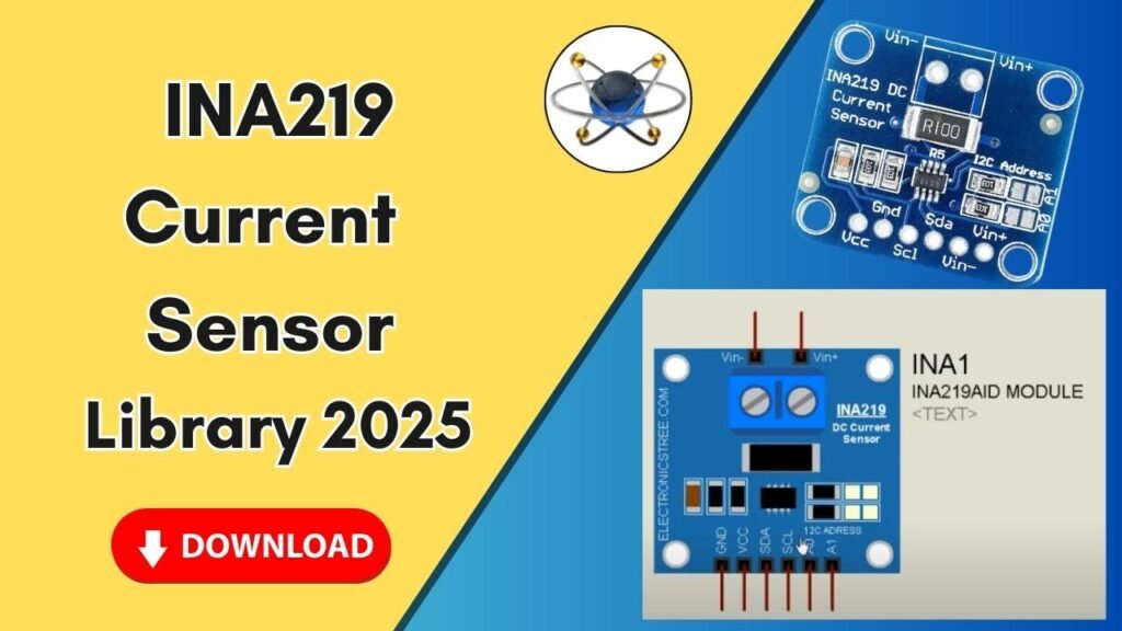
The INA219 is a high-side current sensor that allows you to measure voltage and current with high accuracy. It communicates through the I2C interface, making it suitable for interfacing with microcontrollers like Arduino. This sensor is widely used in power management applications, battery monitoring, and other electronic projects that require precise current measurement.
Steps to Add the INA219 Current Sensor Library to Proteus
Step 1: Download the Library Files
Before installing the INA219 sensor library, you need to download the necessary library files. The download link is provided in the description of the video or can be found on trusted sources online.
Once downloaded, extract the ZIP file, and you will find two folders inside:
- Library
- Models
Step 2: Copy the Library Files to Proteus
Now, let’s move the files to the correct locations within the Proteus software directory.
1. Move the Library Files
- Open the extracted folder and navigate to the Library folder.
- Copy the files inside this folder.
- Locate the Proteus software icon on your desktop.
- Right-click on it and select Open file location.
- Go one step back to the Proteus 7 (or your version) main folder.
- Find and open the Library folder.
- Paste the copied files here.
2. Move the Models Files
- Go back to the extracted folder and open the Models folder.
- Copy the files inside it.
- Navigate to the Proteus main directory again (as done earlier).
- Locate the Models folder.
- Paste the copied files here.
Step 3: Restart Proteus
For the newly added library to be recognized, you must restart Proteus:
- If Proteus is already open, close it completely.
- Restart Proteus to allow it to load the newly added INA219 library.
Step 4: Search and Place the INA219 Current Sensor in Proteus
Once Proteus has restarted, you can now access the INA219 current sensor for circuit design.
- Open Proteus and go to the Components Library.
- Search for INA219 in the search bar.
- You will see multiple current sensors in the list. Select INA219.
- Double-click on it and then click OK.
- Place the INA219 sensor onto the Proteus workspace.
- Zoom in to inspect the pin configuration and make the necessary connections.
Step 5: Understanding INA219 Pin Configuration
The INA219 current sensor has the following pin configuration:
- VIN+ and VIN-: Connects to the load in series for current measurement.
- VCC: Power supply (typically 3.3V or 5V).
- GND: Ground connection.
- SDA & SCL: I2C communication lines for interfacing with microcontrollers.
- A0 & A1: Address selection pins for I2C communication.
Testing the INA219 Sensor in Proteus
Now that you have successfully added the INA219 sensor to Proteus, you can integrate it into your circuit design. If you are using Arduino, ensure you establish the correct I2C connections (SDA, SCL) and write the appropriate Arduino code to read the current values.
Conclusion
Adding the INA219 Current Sensor Library to Proteus is a simple but crucial step for electrical engineers who want to simulate circuits before implementation. With this library, you can easily measure and monitor current in your simulations, making it easier to design efficient power systems.


