Getting Started with Proteus: A Beginner’s Guide

The Proteus Design Suite is a powerful tool used worldwide for designing and simulating electronic circuits. Whether you’re an engineering student, a hobbyist, or a professional, Proteus provides the perfect platform to design circuits, test them virtually, and even create PCB layouts without the need for physical components initially. This article serves as a beginner’s guide to Proteus, walking you through the software’s essentials and guiding you in creating your first project.
What is Proteus?
Proteus is a software suite developed by Labcenter Electronics. It combines tools for schematic capture, simulation, and PCB design into one integrated environment. The software is widely used in academia and industry for creating electronic designs.
Components of Proteus
Proteus ISIS (Intelligent Schematic Input System):
- Used to design and simulate electronic circuits.
- Allows users to test designs with virtual components, including microcontrollers like Arduino, PIC, and AVR.
- Ideal for learning circuit simulation basics.
Proteus ARES (Advanced Routing and Editing Software):
- Used for PCB layout design.
- Supports routing tools, multi-layer PCB designs, and auto-routing.
Why Use Proteus?
Proteus offers several advantages, making it an essential tool for anyone interested in electronics:
- Error Reduction: Test and debug your circuits virtually before moving to hardware.
- Cost Efficiency: Save money by avoiding unnecessary purchases of components for untested designs.
- Educational Use: Ideal for students learning basic and advanced electronic concepts.
- Diverse Applications: From simple LED circuits to advanced microcontroller projects.
For beginners, Proteus is particularly useful as it simplifies complex tasks, providing a smooth learning curve.
How to Install Proteus
Here’s a detailed walkthrough of the installation process:
Download:
- Visit the official Proteus website.
- Choose the appropriate version for your operating system.
Install:
- Run the downloaded installer.
- Select the components you wish to install (Proteus ISIS and ARES are typically included).
- Follow the on-screen instructions to complete the installation.
Activate:
- If you have a license, enter your key during installation.
- For trial versions, you can skip this step, but some features may be limited.
Navigating the Proteus Interface
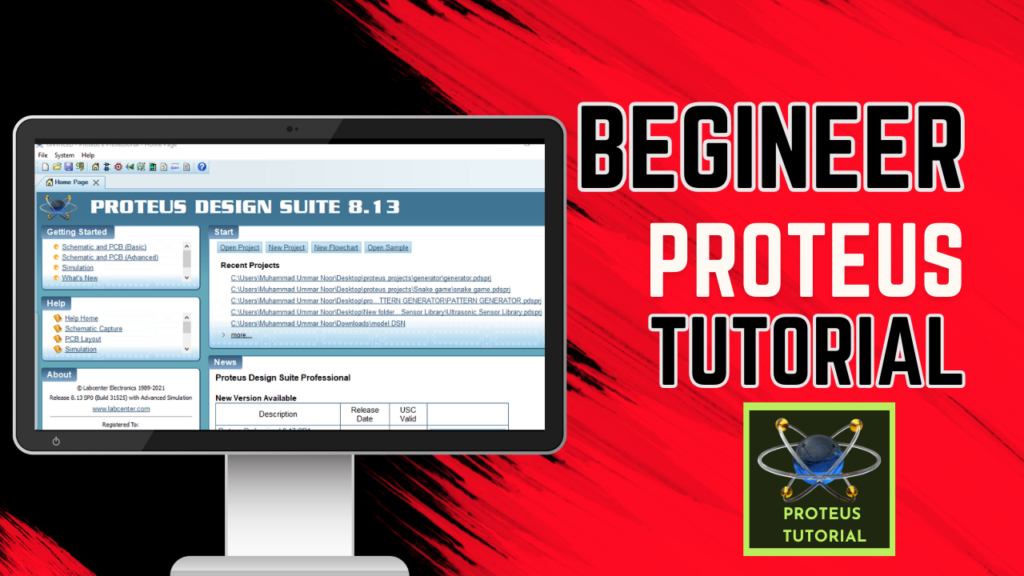
When you first open Proteus, you’ll see a clean, well-organized interface. Here’s a breakdown of the key sections:
Toolbar:
- Tools for adding components, connecting wires, and running simulations.
- Includes options to save, open, and manage projects.
Workspace:
- The primary area where circuits are designed.
- You can drag and drop components, connect them, and arrange them logically.
Component Library:
- Access thousands of pre-built components, from basic resistors to complex microcontrollers.
- Search for components using keywords or filters.
Simulation Controls:
- Buttons to start, pause, and stop the simulation.
- Allows real-time observation of circuit behavior.
By familiarizing yourself with these sections, you’ll be able to navigate Proteus with confidence.
First Steps in Proteus
Step 1: Launch Proteus ISIS
Once installed, open the Proteus ISIS tool. You’ll see the workspace and tools necessary for circuit design.
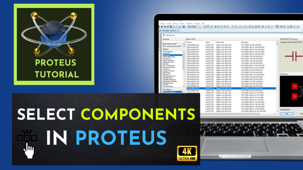
Step 2: Select Components
- Click the ‘P’ button in the component library to search for components.
- For example, search for “LED” or “Resistor” and add them to your workspace by clicking Place.
Step 3: Arrange Components
- Drag the components to organize them logically on the workspace.
Step 4: Connect Components
- Use the wire tool to connect components:
- Click one component’s pin and drag the wire to another pin.
- Ensure connections are accurate to avoid simulation errors.
Step 5: Run Simulation
- Click the play button to start the simulation.
- Observe how your circuit behaves in real-time.
Practical Example: Simulating a Simple LED Circuit
Here’s an expanded guide for a basic LED circuit simulation.
Required Components:
- 1x LED
- 1x Resistor (330 ohms)
- 1x DC Power Source (5V)
Step-by-Step Instructions:
- Place Components:
Add an LED, resistor, and a DC power source to your workspace.
- Connect the Circuit:
Attach one end of the resistor to the positive terminal of the power source.
Connect the other end of the resistor to the LED’s anode (long leg).
Connect the cathode (short leg) of the LED back to the ground terminal of the power source.
- Start Simulation:
Click the simulation play button.
Observe the LED lighting up, indicating a successful circuit.
- Experiment:
Change the resistor value and observe how the LED’s brightness varies.
Troubleshooting Tip:
If the circuit doesn’t work, double-check the connections and ensure the power source is active.
Advanced Example: Blinking LED with a Microcontroller
Once you’re comfortable with basic circuits, try using a microcontroller like an Arduino in Proteus.
Components Needed:
- 1x Arduino UNO
- 1x LED
- 1x Resistor (220 ohms)
Steps:
- Add the Arduino UNO from the library.
- Connect the LED to a digital pin (e.g., pin 13) via a resistor.
- Use the “Edit Firmware” feature to upload a basic blink sketch:
void setup() {
pinMode(13, OUTPUT);
}
void loop() {
digitalWrite(13, HIGH);
delay(1000);
digitalWrite(13, LOW);
delay(1000);
}
- Run the simulation to see the LED blink.
This advanced project showcases the power of Proteus in simulating embedded systems.
Tips for Success in Proteus
- Use the Help Menu: Proteus includes detailed documentation to help you learn.
- Explore Tutorials: Experiment with built-in examples to understand complex features.
- Keep Projects Organized: Use layers, labels, and comments to maintain clarity.
- Save Frequently: Protect your work from accidental loss by saving often.
Conclusion
Proteus is an indispensable tool for beginners in electronics, offering a seamless way to design, simulate, and test circuits. By mastering the Proteus basics outlined in this guide, you’re ready to explore more advanced projects and applications. Start experimenting today, and unlock your potential in electronic design!


Plunge into the vast galaxy of EVE Online. Start your journey today. Explore alongside millions of players worldwide. Download free